Well done to everyone who is continuing to work on this project - each time I see a new post I get excited all over again!
I’ve installed CadQuery and am exploring it. It looks like people are already on task of generating the parts (and way more skilled than I am!) but if there are any simple bits that I can tackle, I’m open to giving it a go. I tried to explore the parts already in the repository but wasn’t sure where to access the imported local ‘utilities’ library.
I have access to a small 3D printer and a laser cutter if we need to test any parts etc.
Help with CAD design would be great actually. For your start with CadQuery, I have marked the easy-to-draw parts with a (cherries) icon in our list of custom parts. Namely: the input control knob; a carrying handle; cable routing aids; and an electronic enclosure. These parts will not be needed for the prototype but later for a production model, so there is no rush at all for that work. But they are relatively straightforward parts that are good for learning CadQuery alongside.
Some tips for a start with CadQuery:
It’s definitely not the easiest tool to learn, but unlike any 3D CAD drawing tool it enables completely parametric designs, which is a big deal for a machine like this. For example, in the future it might allow us to create a machine for walnut sorting by just changing a few parameters and letting the CadQuery script calculate the parts to print.
If you work on a part, you can first create the geometry with fixed numbers as arguments for 3D object creation, rather than making everything parametric from the start. Also at the start you don’t have to try to put everything into classes and methods like I did – all in one Python file is fine. If you stop there, it’s already helpful for me as I’ll have the ideas in code and just need to wrap it into a parametric design and a class structure. You can do that as well of course; but doing it all at once together with trying to get the geometry right and learning CadQuery could be a bit too much complexity to handle at once.
Just save all the files you see in this directory into one directory on your computer, and the import utilities line will be resolved automatically from the utilities.py script in your directory.
The “proper” way to get all these files is of course with this command:
Another bit of progress I just finished the input tube socket part, shown below. Not sure yet about the final measures and angles, but that’s easy to configure for a parametric design. CadQuery source code is available in the repo, as usual.
Now only two more essential parts to go (coffee bean pusher and belt unit) …
I’ve starting working on the belt bracket…
Making a “universal” belt bracket with a small engine mount bracket. First of all because I don’t know yet what type of engine will be used exactly, but also because if ever in the future the engine needs to be replaced and the new one has to be slightly different it’s easier to just make a new engine mount bracket to be mounted on the belt bracket than requiring a whole new belt bracket …
Still quite a bit to do though. Couldn’t work on it last weekend since our webshop went down and it took me two days of struggle to get it back up and running. But here’s a sneak preview of half a bracket.
Of course all sizes are easy adjustable since they’re input parameters
Great work! And even with a belt tensioner already. Looks like you took some inspiration from the mini conveyor design, which is also my favorite. Too bad that’s not a parametric design already, or we could have used it more or less as it is. It will be really helpful to have this as a parametric belt unit, as even one sorter will need two different belts.
You can leave out the motor mount bracket. I started to design that yesterday, and it will be completely independent of the belt unit. That means, I propose that it will be mounted to the machine sidewall and coupled with the belt roller axle using a loose coupling with a drive profile (see part “belt unit motor coupling”). (BTW, the motors we’ll use are NEMA17 sized stepper motors. They come in various lengths, and I don’t yet know which we need; probably 34 mm or 40 mm.)
I also had a simple idea for how to mount your belt unit to the machine wall, using two M6 bolts supported by 3D printed parts (see concept belt unit mount). It just requires a single hole on each of the two XZ plane faces of each of your belt bracket halves.
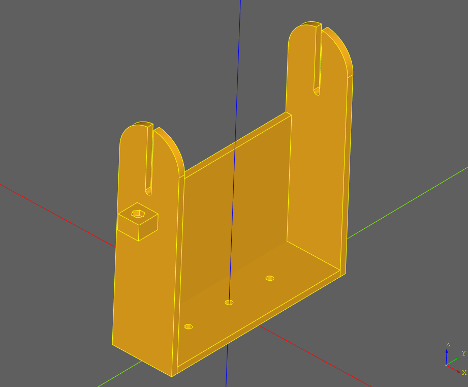
Thank you for your support and encouragement, Mattias - I do feel like I still have a long way to go and it’s totally cool if none of my stuff makes the final cut, but here is what I have been working on so far for the input selector…
It isn’t yet in classes etc. but I have at least pulled all the dimensions into variables.
I also wasn’t sure what electrical selector it would sit on, so that of course will need changing.
Well done to yourself and aqdennis… This thing is really coming along now!
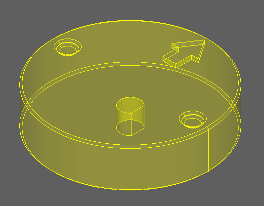
Oh, one more part! Such a fun way to work together Simplified collaboration seems to be another advantage of parametric designs – we don’t have to communicate exact dimensions or agree on them, as these can be set right before manufacturing the parts.
Your input wheel is good, we can totally use it for the final design. It will sit on the axle of some sort of potentiometer or rotary encoder. So as long as the diameter, height and cutoff of the mount hole can be adjusted with variables, it will fit.
When you feel your code is ready, you can send a pull request. Or if you’re not comfortable with git yet, just post your code here and I’ll add it to the repo.
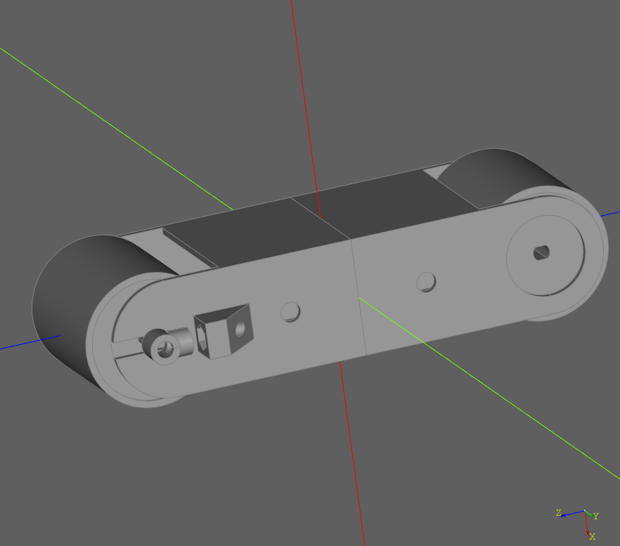
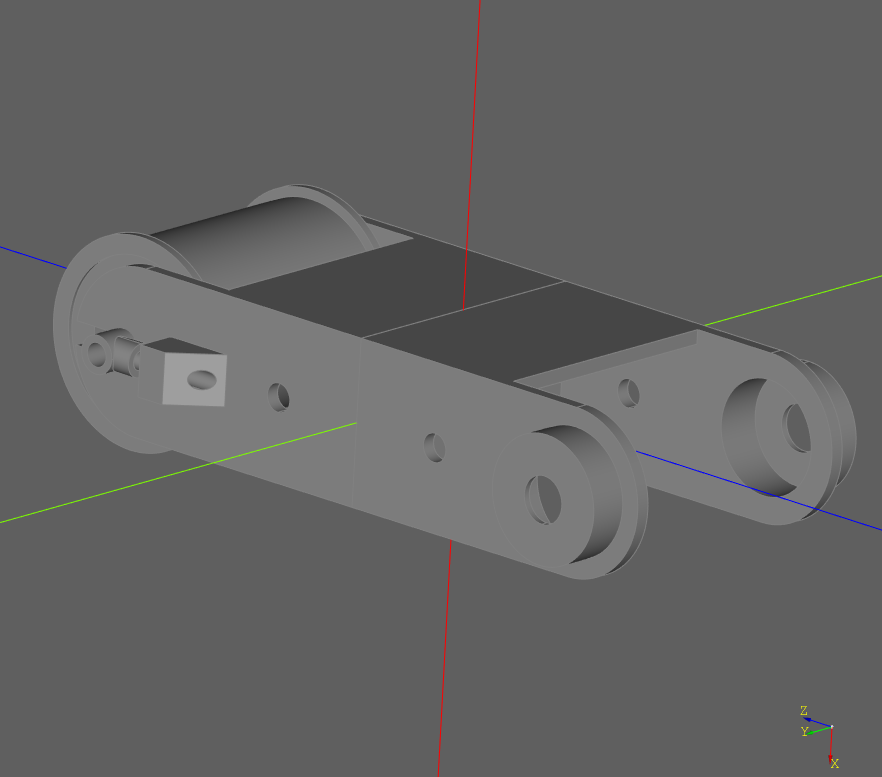
Made it a late nighter yesterday so I have pretty much the 2 halves of the belt bracket, 2 rolls (one for bearings, one without bearings) and 2 connecter pieces to connect the belt tightener screws to the axis of the roll to push out.
Now the question is … would you like to have all of it in 1 class or all separate classes ? Considering you won’t print it all at once I guess all separate classes…?
Awesome, that’s great progress. CadQuery can be a bit addictive, right?
I propose to put it all into one class, mostly because the parameters overlap so much that it makes sense to have them in one place only.
For printing separately, the simplest solution is to export the different objects to separate STL files first. In cq-editor, you’d click on the object to export, then select “Export to STL …” from the menu, then do the same for the other objects. We’d automate that later by adding an export function to classes, but no need for that right now.
You might want to look at creating the complete belt unit as a CadQuery Assembly object in your class. It allows to arrange the individual parts with constraints. But it seems also a complex API, and could be overkill for right now.
Ok, I finished putting it all in 1 class. I’ve tried to commit/push it to the repository, butit seems I don’t have write access there…
I can think of some more improvement … maybe have sides slightly sticking out above the belt level to avoid beans falling of from the side? And I guess I can make the belt rest a bit longer, the gap between the belt rest and the rollers is quite big.
With respect to the rollers…
Motor side: motor axis is fixed in the roller, I assumed a bearing would be used attached to the bracket hence I left a rather large whole in the bracket to mount a bearing in after which the motor axis (and the opposite axis at the other end of the roller) goes through the bearing
Non-motor side: the belt tensioning system won’t allow for a bearing in the bracket, hence the bearing must be in the roller. so the roller on this side of the bracket has 2 indented circles to fit bearings in.
Ok, added you as a collaborator now. You’ll have to accept the invite on the Github platform before you can push your commits.
For the slow, upper belt that would be needed, yes. For the faster, lower belt we cannot use that, as the bean pushers need to be able to do their work. We might however need small ridges at the edges of the rollers to keep the belt in place; not sure yet though.
Mounting a bearing into the belt unit bracket makes sense in my mind. To hold them in place, could you add a cylindrical covering over these bearings? So the bearings would be pushed in from the inside towards the outward facing side of the belt unit bracket, and would rest against a back wall of the cylindrical covering once they are flush with the inside wall.
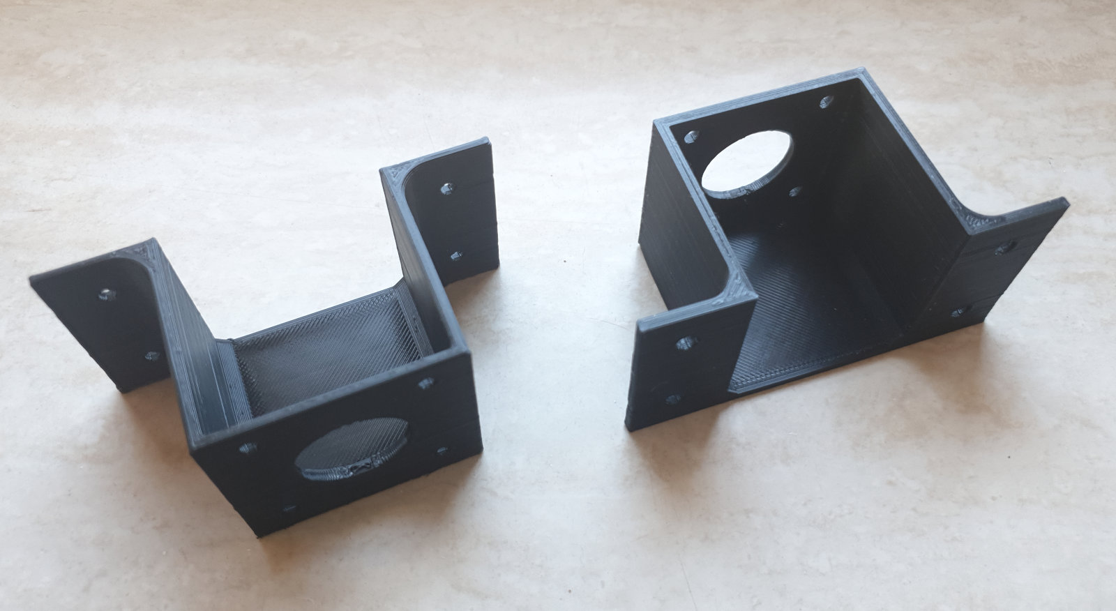
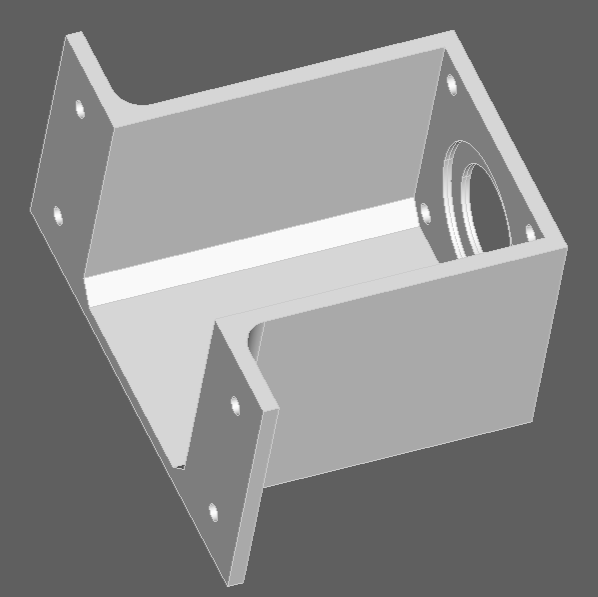
P.S.: Here’s my new part, the motor mount bracket for the belt stepper motors.
Perfect. I will add the covering for the bearings as well as ridges for the rollers through an extra parameter so that they can be printed…or not.
Though in my experience if a belt has the habbit of going to one side it’s usually because the rollers are not well aligned and ridges won’t resolve it. But it won’t hurt if I just add them and then we’ll see if they’re needed or not.
It’s a great part, thank you a lot! Also your code is well structured and readable, thanks for putting in the effort
I’ll adjust a few things lateron to newer versions of CadQuery “conventions” that have been developing on my end. That said, I’m still getting settled into CadQuery, so any conventions are still preliminary … . Won’t touch your few-letter abbreviation variable naming scheme. I see the advantages, as it makes the code really concise … though I still prefer long-form names in my code.
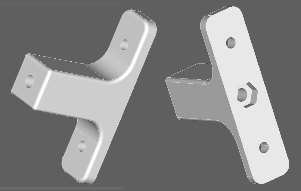
I just committed another small part I made (“bolt mount”, to mount machine units to the walls with a captured M6 bolt inserted into this support part):
So now there are only two essential parts left (motor coupling, pusher module) before I can start with the prototype build. It’s really coming together
Here’s another bit of progress report after a while I finished another part and committed it to the CAD parts directory in the repo. This is the motor coupling that will be used both on the stepper motor and Dennis’ belt unit, with the cogs of the two halves interlocking and handling small radial or axial misalignments of the axes.
With this, only one essential part is left to be designed for a functional prototype, namely the pusher unit with the solenoids to push coffee beans out. But I’m a bit tired of 3D CAD now, so I will first 3D print, order and assemble the other parts of the prototype machine. Let’s see how that goes.
Looks great! Sorry I couldn’t help…I’ve got an eye condition and I am right now recovering from a laser treatment on my right eye. So looking at a computer monitor is quite blurry at the moment, but should be fine again by next week…if you’ve left anything to do for me .
Mostly I selected and ordered hardware, and reworked several parts of the design. The machine will look quite different now:
It’s larger, using a 400×300×220 mm Eurobox for a case.
It uses a notebook (or notebook/tablet hybrid) mounted on top for calculations rather than a Raspberry Pi, as that gives much more MIPS per buck and includes a proper display, keyboard and pointing device.
It has up to four parallel sorting lanes inside now, each with its own RAMPS stepper controller, increasing the possible throughput to (hopefully) 17 kg of coffee per hour.
Finally, the object manipulator units that divert bean to the correct outputs now use stepper motors instead of solenoids.
Details and reasons are as usual under “Concept: Current” in the design document, and feedback / comments on the design are of course welcome.
I also printed a few parts. Here are the stepper motor mounts:
Some big changes! It’s impressive how thoroughly you are documenting the whole development process, well done! Printed parts look great, too. Keep up the good work!
Small question to the coffee roasters and coffee processors here.
Imagine the optical sorter requires you to load a new batch of 17 kg green beans every 1-2 hours (which depends on the throughput we can achieve), and to remove the output box with the sorting results of the previous batch. Would that be acceptable or annoying? In other words, what minimum time duration should a batch have before you have to tend to the machine again for 2-3 minutes to load another batch?
(Background: some more changes in the intended machine setup, leading to this concept).

 .
.